Drawing Robot
AACC Mechatronics Capstone Project, January-May 2022
My goal was to get an ABB IRB 120 industrial robot to draw a picture using multiple colors of dry erase markers. I designed, 3D printed, and developed the marker changer attachment for the robot. I also programmed the robot with assistance from my partner. We programmed the robot to draw the AACC riverhawk logo, Ukraine, as well as a line art drawing.
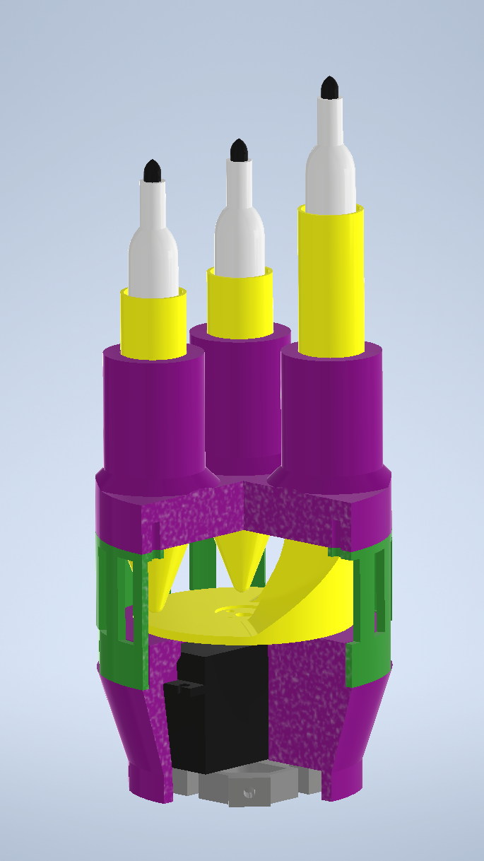
A rendering of the marker changer with a cutout to show the internal servo and cam
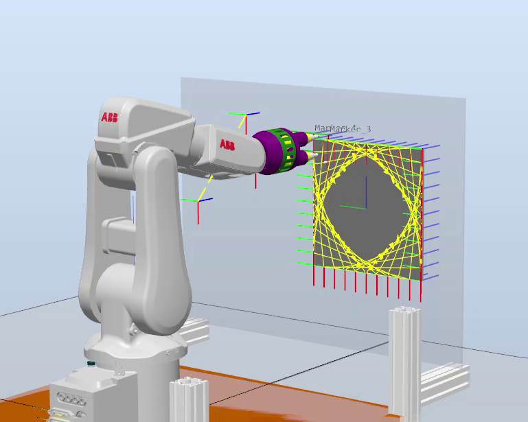
Screenshot of the Robot Studio software used to program the robot
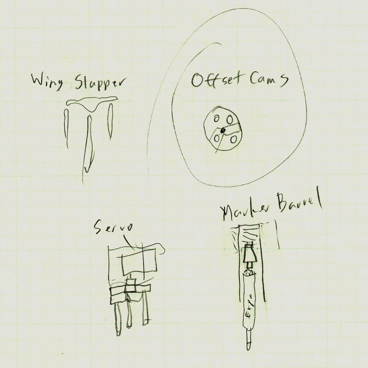
An early concept sketch for the marker changer
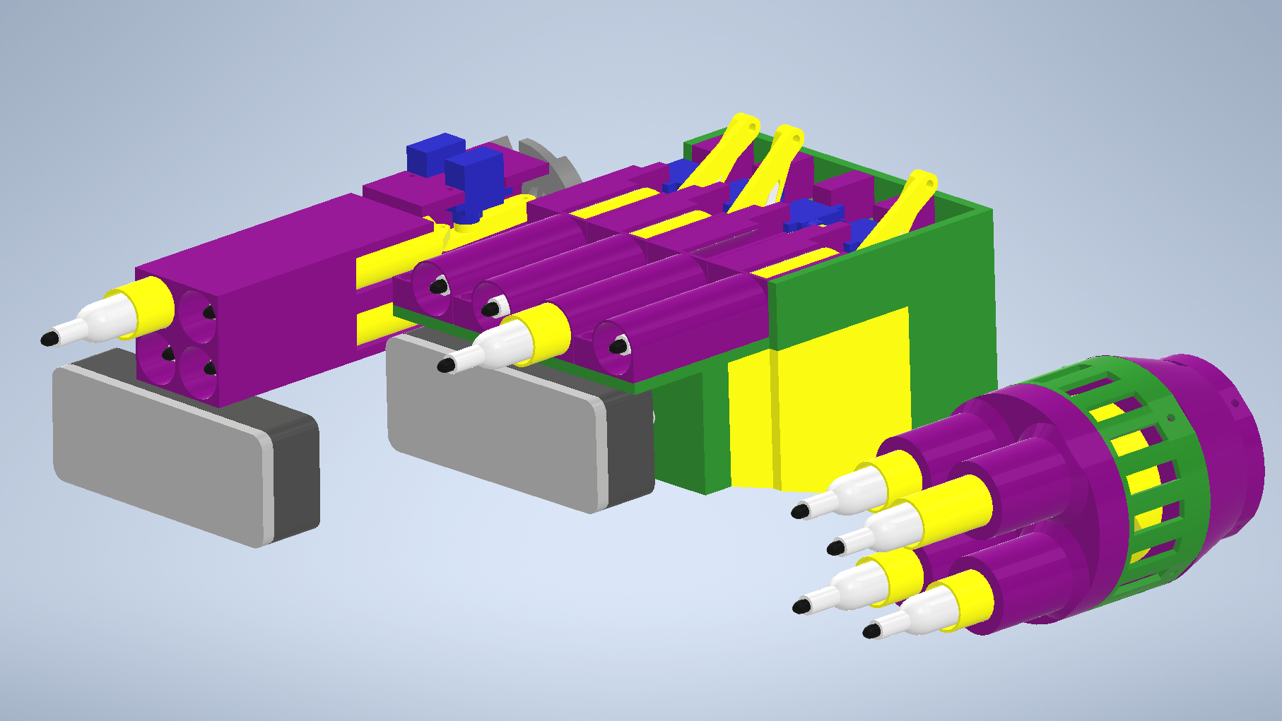
A comparison of the first marker changer (right) with later versions that incorperated an eraser, but never came to fruition
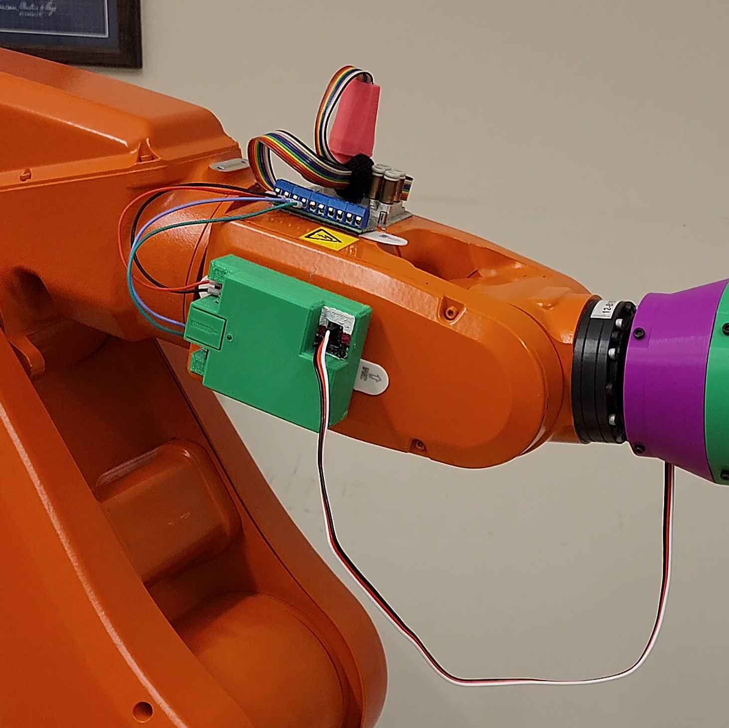
To control the Marker Changer's servo, I built a custom controller that took in 24V and two digital signals and output a 5V servo signal
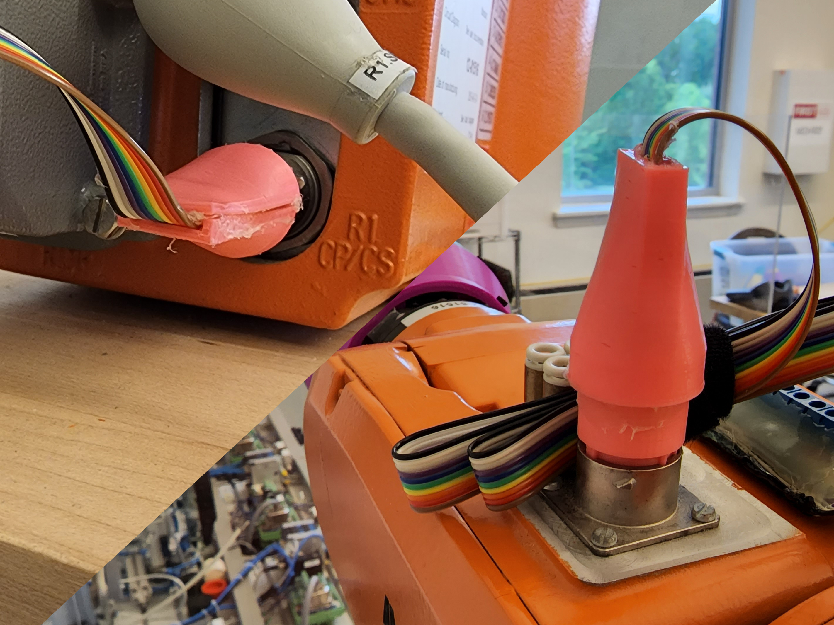
To get power and the control signals to the controller, I designed and printed connectors to plug into the robot's proprietary passthrough port
This Website
Personal Project, Ongoing
I developed this website from scratch in HTML because I found the website builder options lacking in customizability and simplicity. This website is my first, and I taught myself HTML and CSS as I wrote it.
Light Cube
Personal Project, February 2020
This 5×5×5 LED light cube was inspired by one I had seen at AACC. The cube is powered by an Arduino Nano connected to shift registers to handle the additional outputs. I first built a smaller and rougher 4×4×4 cube, and its effects were programmed by modifying the byte sent to the shift registers mathematically. The larger and cleaner 5×5×5 cube included drawing functions to make programming the effects easier.
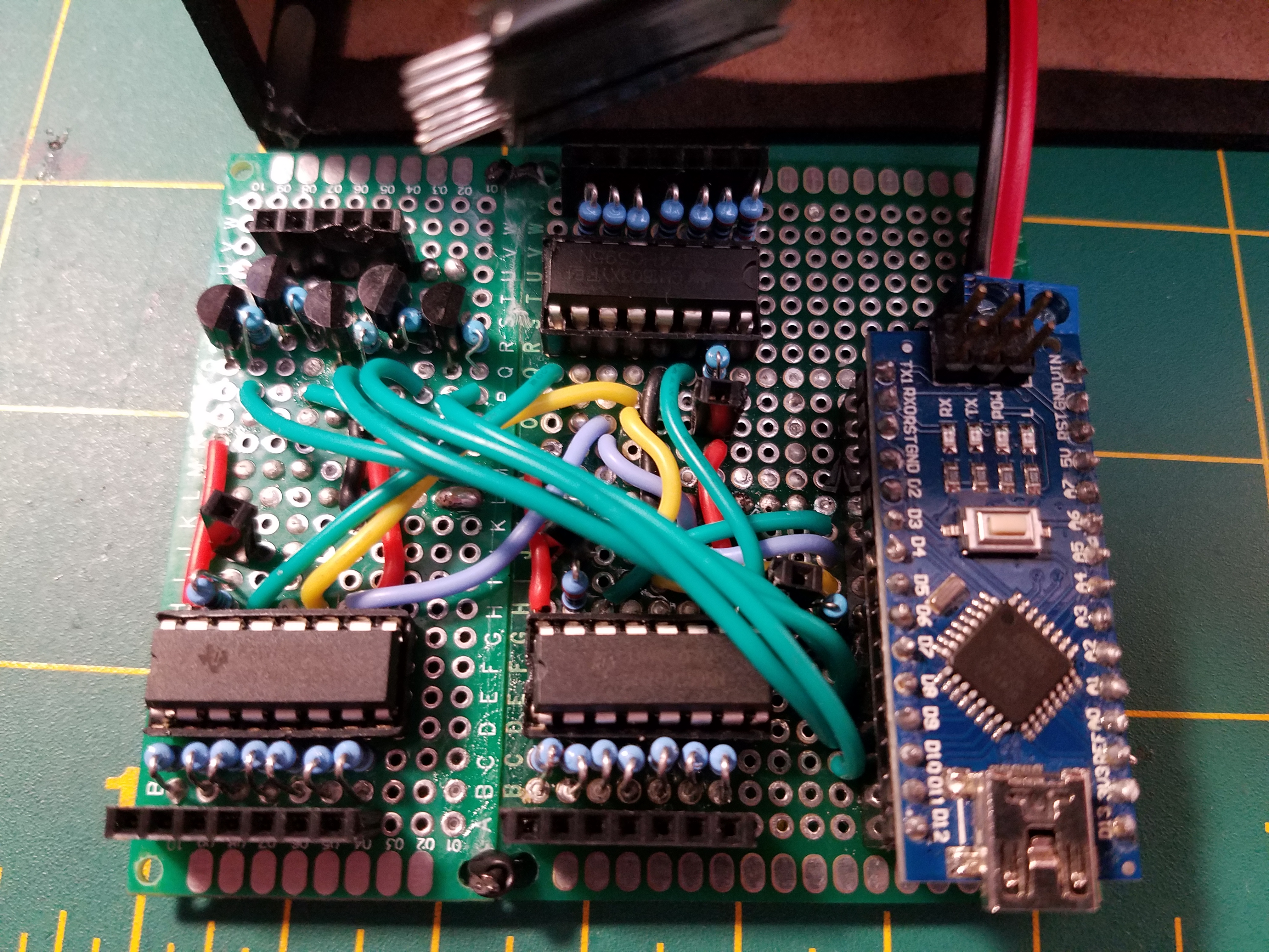
The board for the cube breaks features the Arduino Nano, three shift registers for controlling each column, and five transistors for controlling each layer
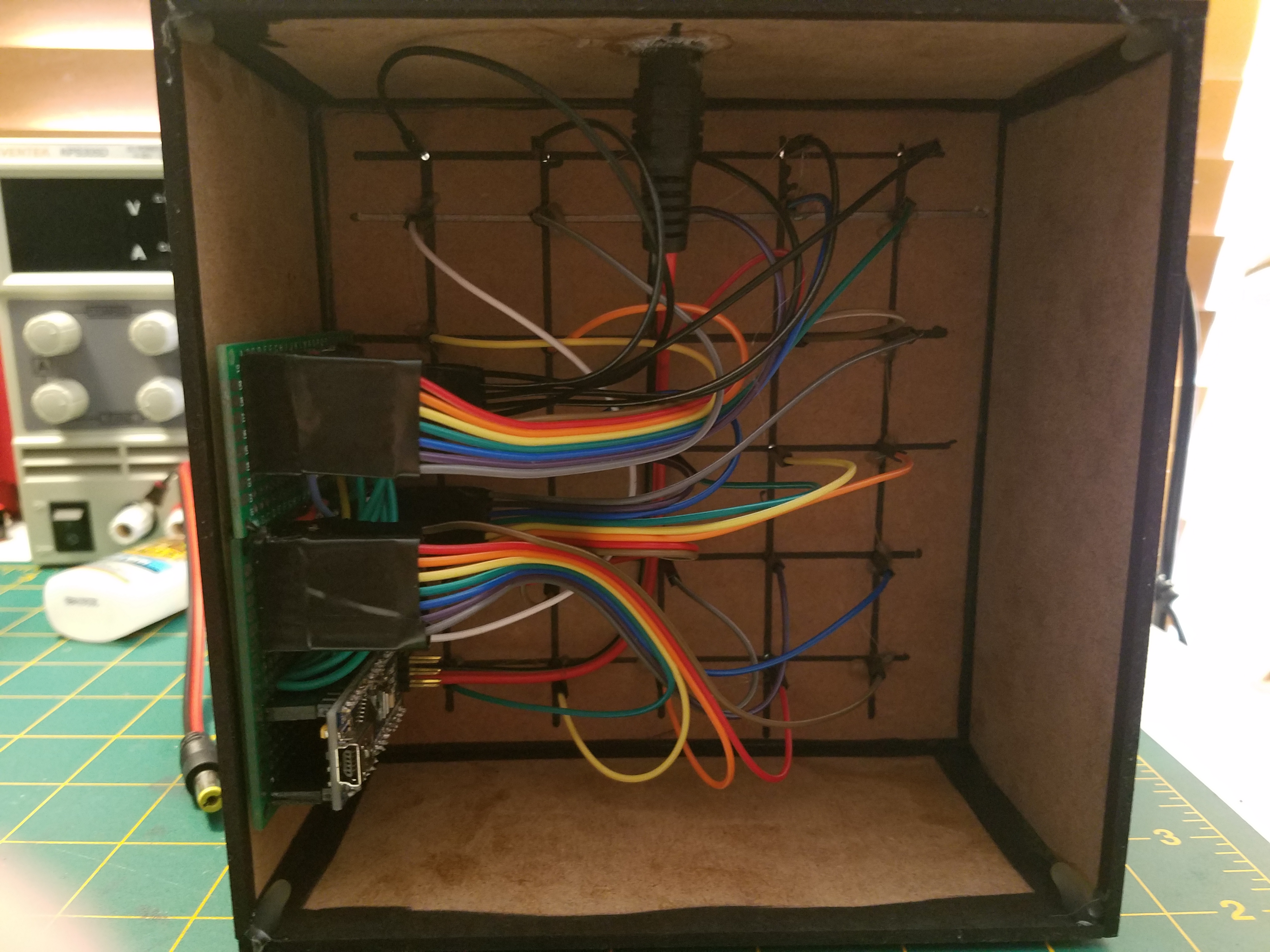
The MDF case that holds the cube contains the board and all the wiring
 Scott Mikutsky